This document is the User Guide of the FSAP/NuSMV-SA platform.
The FSAP/NuSMV-SA platform aims at supporting design and safety engineers in the development and in the safety assessment of complex systems. The FSAP/NuSMV-SA platform has been developed by the Embedded Systems Unit of FBK within the framework of the ESACS project. The FSAP/NuSMV-SA platform is composed of two main tools: FSAP (Formal Safety Analysis Platform), providing a graphical user interface for easier user interaction and NuSMV-SA an extension of the NuSMV2 model checker. Within the framework of the ISAAC European Union project, the platform is being further developed to address the new objectives of the project.
Certain information related to the FSAP/NuSMV-SA platform is not discussed in this document. Please refer to the table below for a list of some the documents describing the platform and their purpose.
|
For information on ... |
Please have a look at: |
|---|---|
|
... what's new: |
the release notes document (release_notes.html) |
|
... downloading: |
the FSAP/NuSMV home page (http://es.fbk.eu/tools/FSAP) |
|
... installing: |
the getting started document (getting_started.html) |
|
... licensing: |
get in touch with the FSAP team (contact_us.html). |
The FSAP/NuSMV-SA platform aims at supporting the formal analysis and safety assessment of (complex) systems. The platform is based on a set of tools (including an extension of the NuSMV model checker) and is based on the concept of a repository. The repository contains the information necessary for the design and safety assessment of systems and is shared between the design engineer (the actor responsible for the design of the complex system) and the safety engineer (the actor responsible for performing safety analysis on the complex system).
The platform is designed to support different phases of the development and safety assessment process and to support different development and safety assessment practices. To achieve these goals, FSAP/NuSMV-SA provides a set of basic functions. These basic functions can be combined in different ways to perform complex tasks. The major benefits from the use of FSAP/NuSMV-SA are the following:
The platform supports a tight integration between the design and the safety teams;
The platform automates (some of) the activities related both to the verification and to the safety analysis of systems in a uniform environment;
The use of the platform is compatible with an incremental development approach, based on iterative releases of the system model at different levels of detail.
The FSAP/NuSMV-SA platform is being developed within the ISAAC Project, a European Union sponsored project in the areas of formal verification and safety analysis. The project builds upon and extends the results of ESACS project. The goals of ESACS were the definition of a methodology that integrates design and safety analysis practices and the development of platform(s) to support the methodology. ISAAC's project goal is to go a step further into the improvement and integration of safety activities of aeronautical complex systems. Potential benefits range from higher confidence in the safety of systems to increased competitiveness of European industries.
The FSAP/NuSMV-SA platform supports the ESACS methodology by automating the steps mentioned above.
A glossary is appended to the end of this manual with a list of terms used throughout. Also, special attention must be paid to the acronym 'SAT' which is used to define a 'Safety Analysis Task' and also the SAT-based verification engine. If no specification is made, the reader should assume SAT to be Safety Analysis Task.
The FSAP/NuSMV-SA methodology describes how to use the FSAP/NuSMV-SA platform. The methodology derives from the ESACS methodology: we present it in the following list using the concepts of phases (set of activities) and activities (activities are not necessarily elementary steps – they are not, however, further decomposed in this document):
Model Capturing: it is the phase, usually performed by the design engineer, in which a formal model of the system under development (system model, from now on) is provided. It is composed of a single activity, Define System Model
Requirements Capturing: it is the phase, performed both by the design and by the safety engineer, in which the properties of the system under development (system model, from now on) are provided. The properties refer both to the behavior of the system in nominal conditions and to the behavior of the system in degraded situations. We distinguish two different activities, namely Define Requirements and Define Safety Requirements.
Failure Mode Capturing: it is the phase, usually performed by the safety engineer, in which the failure modes of the components of the design model are identified. It is composed of a single activity, Define Failure Modes.
Failure Injection: it is the phase, usually performed by the safety engineer, in which the failure modes of the system are injected into the design model. This step generates a new model, called the extended system model, in which components may fail according to the specification of failure provided at the previous step. It is composed of a single activity Extend System Model.
Formal Assessment of the System Model: it is the phase in which the system model and the extended system model are formally checked against a set of properties. We can distinguish two different activities:
Formal Verification: it is the activity, usually performed by the design engineer, in which the model is checked against a set of pre-defined requirements, under the hypothesis of nominal behavior, that is, under the hypothesis that all the components work as expected. This step assures the correctness of the design in nominal situations.
Assess Safety: it is the activity, usually performed by the safety engineer, in which the model is checked against a set of pre-defined requirements, under the hypothesis that the component may fail. This ensures that the system behaves as required in degraded situations (e.g. when some of the components are not working).
All the activities produce artifacts. The artifacts constitute essential information for the system development and are stored in a repository.
The following activity diagram is an example of how the
activities of the FSAP/NuSMV-SA methodology may be interconnected
during a single iteration of the development of a system. (Activity
diagrams are a UML notation similar to flow charts in which we
distinguish activities (rounded rectangles) and artifacts
(rectangles)). The activities have colors that code the
responsibility (blue for the design
engineer, green for the safety
engineer). (Notice that the notation is not standard as, usually,
swimlanes are used in UML for representing the concept of
responsibility.) All the artifacts are marked in magenta.
Notice that the activity diagram below is just one of the
ways in which the ESACS/ISAAC methodology can be applied.
The starting point of the activity diagram is a System Requirements Specification document (SRS) that collects the functional and non-functional requirements of the system under development. (The Requirements elicitation activity is outside the scope of the FSAP/NuSMV-SA platform and it will not be detailed in this document.) When the SRS is available, the FSAP/NuSMV-SA process starts:
Design System Model. The process is initiated by the design engineer, who writes a formal model of the system under investigation (system model) at the level of abstraction required by the current development iteration. In the FSAP/NuSMV-SA line, this activity is carried out using the standard facilities provided by the NuSMV2 model checker. The system model is stored in a SAT (the central data structure of the ESACS platform), that collects all the information related to a system model (e.g. executable specification, safety requirements, analysis performed). The SAT can thus be easily integrated with other tools that may be in use, like, e.g., central repositories, version control systems, etc.
Define Requirements. The second activity is the definition of the requirements of the system model, that are used by the design engineer to assess the design model and that will be used by the safety engineer to assess the behavior of the system model in degraded situations.
Formal Verification. The design engineer is now responsible for verifying the behavior of the system model, by simulating it and/or verifying it against safety and liveness properties. In the FSAP/NuSMV-SA line, this is performed using the standard formal verification functions provided by the NuSMV2 model checker. These functions can be accessed through the FSAP interface, which allows the reuse of the information stored in the SAT. When the design engineer is confident of the correctness of the system model, he passes it to the safety engineer and the SAT becomes the responsibility of the safety engineer.
Define Failure Modes. Since one of the goals of safety analysis is verifying the behavior of the system in degraded situation (i.e. of the behavior of the system under the hypothesis of failure of one or more of the components of the system), the first activity performed by the safety engineer is specifying what are the degraded behaviors of the component of the system model. The activity is carried out by retrieving a set of failure modes from the library of failure modes (Generic Failure Mode Library or GFML, for short). Then a failure mode can be labeled as 'sporadic' (transient behavior) or 'permanent' (persistent behavior) or disabled altogether. The notion of failure modes has been extended to failure sets. A failure set is a group of failure modes which occur under the same circumstances, in other words, a set of failures caused by the same event. Because failure sets are an extension of failure modes, references to failure modes imply failure sets and vice versa. Therefore, defining failure modes may also include defining failure sets. Notice that there may be situations in which this activity can be carried out in parallel with the design activities. This is the case, for instance, when a common reference architecture is already known, e.g. at the second step of an iterative development process. Moreover, this activity may consist of just retrieving information already stored in the SAT, for instance, when some safety assessment activities have already been performed on earlier versions of the system model (e.g. the definitions of certain failures can be re-used from the previous iteration).
Define Safety Requirements. During this step, the safety engineer defines the safety requirements of the system that will be used to assess the safety of the system under development.
Extend System Model (Failure Modes injection). The system model and the failure mode specification are then used by the safety engineer to generate an extended system model, that is, a model in which certain components are enriched with behaviors relative to degraded situations. This can be carried out automatically using the facilities provided by the implementation line.
Assess Safety. The safety engineer now performs analyses to assess the safety of the system. The safety engineer assumes that some of the components may fail and verifies that the behaviors of the system in the degraded situations comply with the requirements of the system. During this step the safety engineer performs simulations, performs testability analysis, computes fault trees, and performs failure mode and effect analyses using both the requirements defined by the design engineer and the requirements defined by the safety engineer. All these operations are carried out using the FSAP/NuSMV-SA platform. Fault trees, for instance, can be automatically computed by NuSMV-SA.
The process ends with the safety engineer providing feedback on the results of the safety analyses. This activity can be carried out using the standard procedures of the organization where the system is being developed (e.g. a written report) and/or by passing the SAT back to the design engineer. The SAT in fact contains the result of the analyses and it may, e.g., contain modified versions of the system model, that suggest how to deal with some specific issues.
Remark 1. The process described above is just one of the ways in which the FSAP/NuSMV-SA platform can be used for the development and safety assessment of complex systems. Some simple variations to the procedure described above are the following:
The responsibility of the activities described above may sometimes be changed, and some of the activities described above as the responsibility of the design engineer may become the responsibility of the safety engineer and vice versa. For instance, there may be situations in which the first formal prototype of the system is provided by the safety engineer (e.g. if the design engineer produces a high-level architecture of the system on paper). Vice versa, the design engineer may be interested in analyzing the behavior of the system in some degraded situations.
Certain degraded behaviors of the components may be defined by the design or by the safety engineer by hand, rather than by using the automatic extension mechanisms provided by the platform. The motivation is that certain complex behaviors may be difficult (if not impossible) to be obtained by retrieval from a library of failure modes. Under the hypothesis that the user provides the specification of the failures following certain simple conventions (e.g. for the names of the failure modes), the manual extensions can be used during safety analysis.
Remark 2. The support granted by the FSAP/NuSMV-SA platform to an iterative process mainly relies on the possibility of (partially) reusing safety requirements and failure modes defined at previous steps. A typical scenario may be the following: when a new model is provided by the design engineer, such a model is incorporated into the SAT. The FSAP/NuSMV-SA platform, at the moment, however, does not provide automatic facilities for change management.
Remark 3. No constraint is put on the way in which the functions of FSAP/NuSMV-SA can be invoked (short, of course, of the trivial constraints imposed by the syntax and semantics of the various commands, e.g. a system model must be defined in order to be verified). The hypothesis underlying this approach is that, by selecting and/or combining the above mentioned functions in different ways, the FSAP/NuSMV-SA can be used in different phases of the process and integrated in different processes.
The short-term drawback is that the NuSMV line will not provide mechanisms for enforcing that a particular procedure and/or a particular process is being followed: that is, it will be up to the user to ensure the FSAP/NuSMV-SA is used in compliance with the procedures and the processes followed for the development of a complex system. (For instance, it is up to the user of the platform to ensure that, e.g., at each iteration of the development process, a fault tree is built for each of the defined safety requirements, should the process require doing so).
In this section we detail the functionality of the FSAP/NuSMV-SA platform and provide more details on how the FSAP/NuSMV-SA supports the methodology described in the previous section.
The FSAP/NuSMV-SA provides the following facilities:
Repository Management. Used for storing all the artifacts produced, it is achieved through the concepts of SAT (Safety Analysis Task) and SAT Manager. See Section "Repository Management: SAT Manager" for more details.
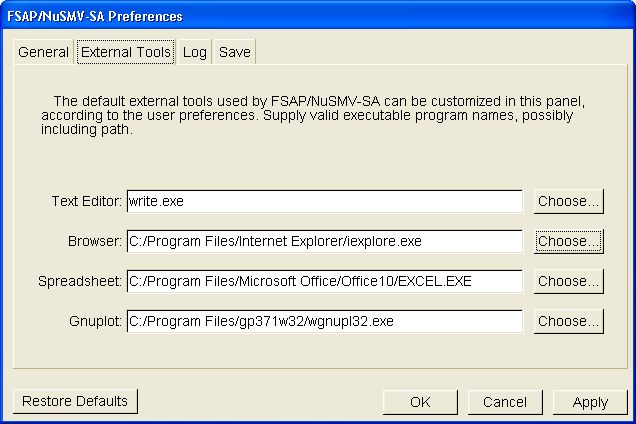
Support for Model Capturing. The FSAP/NuSMV-SA platform is based on the NuSMV2 model checker. The system model specification (and the extended system model specification) is written using the standard facilities provided by the NuSMV2 system, which include a language to define finite state machine specifications. Information about the NuSMV2 language can be found on the NuSMV2 home page, located at http://nusmv.fbk.eu/. FSAP/NuSMV-SA does not provide any specific support for editing system models, short of the possibility of invoking a text editor (of the user's choice): see the "Preferences" section to see how it is possible to specify what editor to use for models.
Support for Safety Requirements Capturing. FSAP/NuSMV-SA provides facilities for editing, storing, and managing (safety) requirements. A safety requirement is characterized by a temporal formula, expressed in the syntax of the NuSMV2 model checker (http://nusmv.fbk.eu/), and some additional information like severity and classification of the corresponding event. Both the properties to be verified (safety properties) and the events to be used for FTA or FMEA construction (top level events) can be stored as safety requirements. See section "Safety Requirements Capturing" for more details.
Support for Failure Modes Capturing. FSAP/NuSMV-SA provides facilities for editing, storing, and managing failure modes and failure sets. Failure modes are defined in a library, called the Generic Failure Mode Library (GFML), and are allocated to modules of the system model. See section "Failure Modes Capturing" for more details.
Support for Failure Mode Injection. FSAP/NuSMV-SA provides facilities for automatically injecting failure modes into the system model. This step generates the extended system model. Users can control the location of the extended system model. See Section "Failure Modes Injection" for more details.
Support for Formal Assessment of the Model. FSAP/NuSMV-SA provides various facilities for verifying the system model and the extended system model. Computing facilities include simulation, model checking, fault tree construction, testability analysis, and ordering analysis. Interface to analyses is provided by the FSAP/NuSMV-SA interface, in which users can specify the kind of analyses to perform, where results are to be stored, etc. See section "Safety Analyses" for more details. Analyses of the results can be displayed using various ad hoc tools, among them a fault tree viewer that supports a tab-separated format, which is a standard for fault tree tools. See Section "Formal Assessment of the Model" for more details.
The SAT Manager is the central repository of all the information that is defined and produced using the FSAP/NuSMV-SA platform. In particular, the SAT contains the following information:
System model (SM)
Failure Modes/Failure Sets defined for the SM
Messages and Message classes defined for the SM
Safety Requirements associated to SM/ESM
Extended System Model (ESM), generated from the above SM
Analysis to be performed on the SM/ESM (Analysis Tasks).
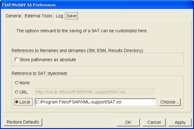
A SAT is stored using the XML format. The XML format can be converted into a more user-readable form using, e.g., style sheet: in particular, a SAT can be associated to a style sheet (possibly stored at a given URL), which contains directives to visualize the SAT as an html document. In this way, the user can transparently load a SAT using an html browser. User-defined display styles can be realized by changing the style sheet.
Failure modes are introduced in the analysis process in order to describe and analyze behaviors related to malfunctions of components (e.g. what happens to the system if a valve remains “stuck open”?). As a general policy the nominal and failure behaviors of components have been clearly separated. In the FSAP/NuSMV-SA, this separation is provided by allowing users to specify the nominal behavior in a system model, and then declaratively specify what failures are to be injected into the System Model, and finally providing an algorithm for automatically injecting those failures into the system model (extended system model). A probability value can also be assigned to a failure mode, which will be added to the extended system model. The probability will be used by NuSMV-SA to calculate the probability of a TLE during fault tree analysis. Failure modes can be defined as 'sporadic' or 'permanent', which is reflected in the extended system model. Sporadic failures can fail and then return to the nominal state, while permanent failures remain failed after having failed once. Failure variables are identified with naming conventions, i.e. the suffix “_FailureMode” and "_SporadicFailureMode" for sporadic failures.
The Failure Modes provided by NuSMV-SA include:
stuck_at: output gets stuck at a particular value
inverted: the output of a Boolean variable is inverted
non_determinism: non-deterministic (random) output
ramp_down: output of an integer variables decreases by a fixed amount each step, down to a bottom value
glitch: delivering of a wrong (random) value for a limited number of steps
When specifying the failure modes, the user selects from a list of failure modes and decides which of them to inject in a given system model. Some of the failure modes require additional parameters (e.g. value to which a valve is stuck at). Failure mode selection is part of the Safety Analysis Task (SAT) definition.
The grouping of commonly caused failure modes can produce failure sets. A failure set is composed by adding failure mode instances from the data dictionary, which will have been propagated by the extended system model (so failure sets must be added after the model has been extended). Failure sets can be comprised of instances from sporadic failures ("_SporadicFailureMode") and permanent failures ("_FailureMode"). Failure sets can also be defined as 'simultaneous' or 'cascading', which implies that all failures in the set occur simultaneously with the "common cause", or that the failures occur within a range of timesteps after the "common cause", respectively. If the user defines the failure set as cascading, they can then define the first and last timesteps (after the "common cause"), between which the given failure must occur. Failure sets can also be added by importing an XML file of failure sets and the failure modes that they contain. The new failure sets will be injected into the System Model, like the failure modes above, when the Extended System Model is regenerated. It should be noted that, not all Failure Set attributes defined in FSAP are defined in the Failure Set XML format, so by exporting and importing some information might be lost.
The list of failure modes that can be defined by the user is stored in the GFML (Generic Failure Modes Library). The GFML contains a declarative specification of the failures that can be defined by the user: such specification includes both information about the characteristics of the failure (e.g. name, parameters) and information about the behavior of the component when the failure is active. The automatic injection of failure modes into a System Model uses the information stored in the GFML.
Remark. If a failure mode or failure set is changed, the user is responsible for
synchronizing the failure mode/set with other instances of the failure mode/set in the SAT.
This will usually be the case when changing between 'sporadic' and 'permanent' for failure modes, and
between 'simultaneous' and 'cascading' for failure sets.
For example, assume a failure mode, FM1, is originally defined as 'permanent'. Then an instance
of FM1, instance.FM1_FailureMode, is used in a message. If FM1
is later changed to 'sporadic' (from permanent), the user is responsible for updating the message
to instance.FM1_SporadicFailureMode, because FSAP is not currently able to synchronize failure
modes with every failure mode instance.
The Failure Modes defined during the Failure Modes capturing activity are injected into the System Model in order to generate the Extended System Model. This can be achieved by the user, simply by clicking "Generate ESM" in the FSAP "Analysis" menu. FSAP now also takes responsibility for keeping the ESM up-to-date. If the ESM is needed -- in an analysis task or the data dictionary for example -- FSAP checks that the ESM is current and if necessary re-generates the ESM. The model extension is completely automatic and no further interaction with the user is necessary. In the event that the extension process is not accomplished, the user receives notification of the failure. However, when the extension is successful, the Extended System Model will contain all the symbols necessary to deal with possible failure behaviors of the system. It is now possible for the user to set up Analysis Tasks for reasoning about such failure behaviors.
The extension algorithm not only injects the defined failure modes into the System Model in order to engender the Extended System Model. It also enriches the Extended System Model with symbols that track the number of failures during the execution of the model, or the maximum duration of a failure. Users can take advantage of these automatically defined variables for controlling in a finer-grained fashion the failure behaviors of the system during the execution of Analysis Tasks. The variables are:
_FailureMode_duration variable defined. This variable is optional and is globally
set in ESM Preferences. It is disabled by default,
and if enabled the default MAX value is 10.Such variables can be freely referenced within the formula of Safety Requirements, and used as standard NuSMV variables. Do remember though, that they do not appear within the nominal System Model. Currently no GUI is available for controlling them but it is planned for the next release of the platform. At the moment manual reference inside the Safety Requirements is the only means of exploiting this feature.
Verification, for some analyses, can be done using either the BDD-based or the SAT-based engine in NuSMV-SA. More details on how this is implemented are provided later when describing particular analysis tasks. The analyses which can be performed using NuSMV-SA include:
Random or user-guided simulation of (extended) system models.
Formal verification of system models and extended system models against properties expressed in temporal logic, either CTL or LTL. This kind of verification is supported by the model checker of NuSMV2.
Fault Tree Construction, i.e. generation of minimal cut sets (MCS) from a given TLE and collection of the results in a fault tree. This approach mainly focuses on the qualitative aspects (i.e. finding MCS). The generated fault trees have a flat structure, namely the structure of the generated fault trees is an “or-and” structure (a disjunction of all the minimal cut sets). No bound is put on the number of basic events a given MCS can be made of. Fault trees can be exported to file with the format used by the commercial tool FaultTree+, and also visualized with a fault tree displayer integrated into the NuSMV-SA platform. The fault tree can also display the probability of all the events in the tree, given that the probability for failure modes/basic events has been defined.
Various detailed analyses can be performed on the minimal cut sets associated to fault trees. In particular:
Minimal Cut Set Trace Extraction. NuSMV-SA provides a trace for each minimal cut sets it generates. The trace shows how the TLE is reached, given a particular configuration of failures determined by the MCS.
Ordering Analysis. Given a MCS (e.g. obtained as result of fault tree analysis), it is possible to compute the ordering in which the basic events have to occur in order for the corresponding TLE to show. The result of ordering analysis can be represented by a set of precedence graphs showing the dependencies between failure events (e.g. an event may occur before, after, or simultaneously with another one). Each precedence graph shows one possible alternative. If basic events may occur in any order, the set of precedence graphs is empty.
Testability Analysis, both Fault Isolation and Fault Detection can be done on (classes of) messages. Fault Isolation Analysis takes a message as input and generates a fault tree as output. Fault Detection Analysis takes a message as input and implicitly all failure modes, and then generates a tab-delimited text file as output, which associates failure modes with the messages selected.
This section describes the components of the FSAP/NuSMV-SA platform and describes how to use the platform.
The different components of the FSAP/NuSMV-SA platform can be described by the following architectural diagram, where:
filled rectangles represent architectural components
green arrows represent data flow
red dashed arrows represent control flow
(To simplify the diagram, not all data and control flows are shown.)
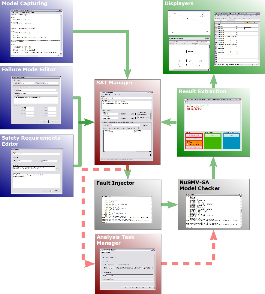
Some of the components (i.e. Model Capturing and Fault Injection) are standard components (i.e. a text editor) or are not meant for the user to interact (Fault Injector is a batch program): they will not be described in this document. The remaining components require (or allow) user interaction and they will be described in more detail. In particular:
SAT Manager. The SAT manager is the core of the interaction with FSAP/NuSMV-SA. From the SAT manager it is possible to control all the interaction with the system. It is described in more details in the "SAT Manager" section.
Failure Modes Editor. The Failure Modes Editor allows the user to specify what failures are to be injected in the system model. It is described in the "Failure Modes Editor" section.
Failure Sets Editor. The Failure Sets Editor allows the user to define a failure set by grouping already existing failure modes which are caused by the same event (e.g. engine burst). It is described in the "Failure Sets Editor" section.
Messages Editor. The Messages Editor allows the user to define a message, with the aid of the Data Dictionary, and to define a message type, which adds the message to the message class of the defined message type. It is described in the "Messages Editor" section.
Safety Requirements Editor. The Safety Requirements editor enables the requirements specification of the system model and of the extended system model. They are the basis for the analyses to perform on the model. The Safety Requirements Editor is described in the "Safety Requirements Editor" section. Editing the Safety Requirements is facilitated by the "Safety Patterns Editor" module and by the "SMV Keypad" utility.
Analysis Task Manager. The Analysis Task Manager allows defining, editing, and running all the analyses that have to be performed on the model. The analysis task manager is described in more details in the "Analysis Task Manager" Section.
Results Extraction & Results Displayers. The result extraction and results displayer module allows the user to manage and inspect the results produced by the analyses. The modules are described in more details in Section "Results Extraction & Results Displayer"
The "Data Dictionary Browser", fully described in the "Data Dictionary Browser" section, is available across the platform providing the means for retrieving the symbols defined within the models (nominal and extended) of the SAT.
The activities performed during the user interaction with the platform are logged into the "Log Window", a description of which is delivered in section "Log Module".
The platform can be configured using the "Preferences" module, which is described in more details in the "Preferences Module" section.
Finally, expert users may be willing to interact directly with NuSMV-SA, through its textual interface. Section "NuSMV-SA Commands Guide" describes how it is possible to interact using the textual interface.
The SAT manager (see figure) allows users to manage a SAT and to control all the interaction with the FSAP/NuSMV-SA platform.
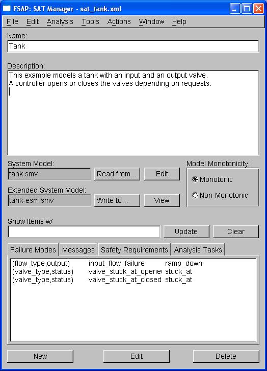
Data Displayed. The SAT manager displays the following information of a SAT:
|
Name |
Name of the current SAT. It can be freely set by the user. |
|
Description |
Description of the SAT. It can be freely set by the user. |
|
System Model |
This group of information displays (and allows to operate) on some basic information concerning the model:
|
|
Failure Modes, |
This group displays (and allows selection of) failure modes, safety requirements, and analysis tasks. In particular we distinguish the following tabs:
|
Commands Available. Actions are performed using the menu items or using the buttons.
The SAT manager menus are organized as follows:
|
File |
> |
New |
Create a new Safety Analysis Task (CTRL+n). It is also possible to create a new Failure Mode, Failure Set, Message, Safety Requirement, or Analysis Task. |
|
|
|
Open |
Open an existing SAT |
|
|
|
Close |
Close the currently opened SAT |
|
|
|
Save |
Save the SAT |
|
|
|
Save As |
Save the SAT with a different name |
|
|
|
Revert to Saved |
Revert to the last saved version of the SAT. |
|
|
|
Import FS mapping... |
Import an XML file with failure set/failure mode mappings. |
|
|
|
Export FS mapping... |
Export an XML file with failure set/failure mode mappings. |
|
|
|
View as HTML |
Open XML file containing the SAT with default browser |
|
|
|
Exit |
Exit. Optionally prompt the user for confirmation. If the SAT has been modified ask whether to save it or not. |
|
Edit |
> |
Preferences |
Set user preferences. |
|
Analysis |
> |
Generate ESM |
Generate the extended system model, from the current system model and failure modes. |
|
|
|
Check Property |
Verify the property corresponding to the SR currently selected. |
|
|
|
Compute Fault Tree |
Generates a fault tree from the formula corresponding to the SR currently selected. |
|
|
|
Compute Ordering |
Provides information about the ordering of failures in a minimal cut set. |
|
|
|
Simulate |
Generates the trace of a random execution of the current SM or ESM. |
|
|
|
TDS Analysis (submenu) > |
Fault Isolation. Generates a fault tree from the
formula corresponding to the message or class of messages currently selected. |
|
Tools |
> |
Data Dictionary |
Opens the data dictionary browser. |
|
|
|
Result Displayer |
Opens the tool for displaying the results of the analyses. |
|
|
|
Fault Tree Displayer |
Opens the tool for displaying fault trees. |
|
|
|
Plotter |
Opens the tool for plotting NuSMV traces. |
|
|
|
Text Editor |
Opens the default text editor. |
|
Actions |
> |
Read SM from... |
Choose the file in which the SM is stored |
|
|
|
Write ESM to... |
Choose the file in which the ESM will be written |
|
|
|
Set ESM preferences... |
Set preferences for ESM generation |
|
|
|
Edit SM |
Edit the System Model with the standard text editor |
|
|
|
View ESM |
Edit the Extended System Model with the standard text editor |
|
Window |
> |
Restore initial size |
Resize the window to its initial dimensions. |
|
|
|
Log |
Hide/Show/Iconify log window. |
|
Help |
> |
Contents |
Opens this document |
|
|
|
Release Notes |
Opens information about what's new. |
|
|
|
FSAP on the Web |
Opens the home page of the FSAP/NuSMV-SA tool. |
|
|
|
About |
Shows some information about the FSAP/NuSMV-SA tool. |
The operations in the 'Actions' menu as well as some from the 'File' menu can be performed using the buttons in the SAT Manger. The following list describes them in detail:
|
Read From... |
Choose the file in which the SM is stored. |
|
Edit |
Edit the System Model with the standard text editor. |
|
Write To... |
Choose the file in which the ESM will be written. |
|
View |
View the Extended System Model with the standard text editor. |
|
Show items w/, Update |
Filter the items in the currently shown tab to view only the elements containing the string displayed in the text box. Use the button "Update" to update the view. |
|
New |
Add a new Failure Mode, Message, Safety Requirement, or Analysis Task. The action performed depends upon the current active tab. |
|
Edit |
Edit the selected Failure Mode, Message, Safety Requirement, or Analysis Task. The action performed depends upon the current active tab. |
|
Delete |
Delete the selected Failure Mode, Message, Safety Requirement, or Analysis Task. Optionally the user is prompted for confirmation. Furthermore SRs that are referenced in one or more AT cannot be removed. The action performed depends upon the current active tab. |
Users can use the four tabs to add, delete, and edit respectively, the failure modes, messages, safety requirements, and analysis tasks. When defining or editing failure modes, the Failure Modes Editor is shown. When defining or editing messages, the Messages Editor is shown. When defining or editing safety requirements, the Safety Requirements Editor is shown. When defining, editing or running analysis tasks, the Analysis Task Manager is shown.
The input box "Show items w/" is a filter; it can be used to control what failure modes, messages, safety requirements, or analysis tasks are shown by the panes. Type a string in the input box and click on the "Update" button, to show the items that contain the string typed in the input box.
The FM editor allows users to define and edit failure modes:
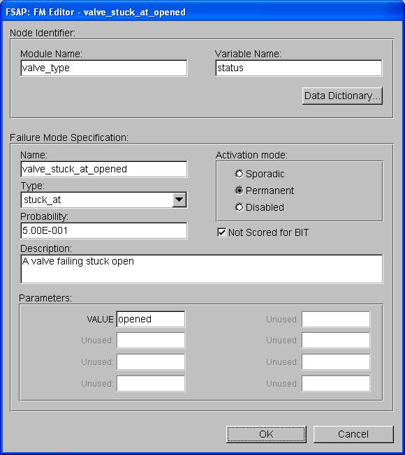
Data Displayed. The FM editor displays the following fields for a given FM:
Name of the variable to extend and the NuSMV module it is contained in
FM type (stuck_at, inverted, non_determinism, glitch, ramp_down, no_failure)
Probability (number from 0 to 1 -- in decimal or scientific notation) that failure mode occurs
Activation mode (sporadic, permanent, or disabled) indicates if the failure is enabled/active, and if so, is the failure persistent or transient
Not Scored for BIT is checked for Built-In-Test failures which should not be calculated in the Fault Coverage Index.
Description (a string)
Optional parameters, dependent on the FM type (e.g., the value at which the variable is stuck for stuck_at type). Unused parameter fields are not active.
Commands Available.
|
OK |
Add (or accept the changes to) the FM to the SAT. |
|
Cancel |
Cancel the operation. |
|
Data Dictionary |
Open the data dictionary browser. If a pair module-variable is chosen within the data dictionary, then it will be automatically copied to the relevant fields of the dialog. |
Separate from the Failure Modes Editor, the Failure Sets Editor allows users to define and edit failure sets by adding and removing failure mode instances.
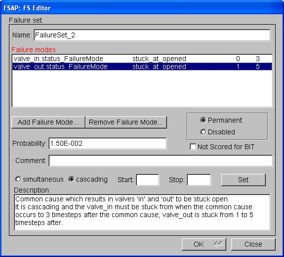
Data Displayed. The Failure Sets editor displays the following fields for a given failure set:
Commands Available.
Add Failure Mode... |
Opens the data dictionary browser. If an instance is chosen within the data dictionary, then it will be automatically copied to the text formula field. See also here. |
Remove Failure |
Removes the failure mode highlighted in the list of failure modes. |
|
Set |
Sets the 'start' and 'stop' timesteps (with values that should be entered in the "Start"/"Stop" text boxes respectively), for a selected failure in a cascading failure set. This is only enabled for cascading failure sets and a failure mode instance must be selected for the values to be set. |
|
OK |
Add (or accept the changes to) the failure set to the SAT. |
|
Close |
Close the failure sets editor and discard changes if any were made. |
The Messages editor allows users to define and edit messages. Message classes cannot be edited, but they can however, be added or removed from within the Messages editor.
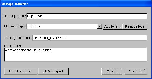
Data Displayed. The Messages editor displays the following fields for a given message:
Commands Available.
|
Save |
Add (or accept the changes to) the message to the SAT. |
|
Cancel |
Cancel the operation. |
|
Data Dictionary... |
Open the data dictionary browser. If a variable is chosen within the data dictionary, then it will be automatically copied to the text formula field. See also here. |
|
SMV_Keypad |
Pop up a window where the user can select the operators commonly used for writing NuSMV properties. See also here. |
|
Add type... |
Opens a new window to define a new message type, which is added to the SAT. |
|
Remove type |
Removes the type currently shown in the 'Message type' scrollbar from the SAT. |
The SR editor allows users to define and edit safety requirements.
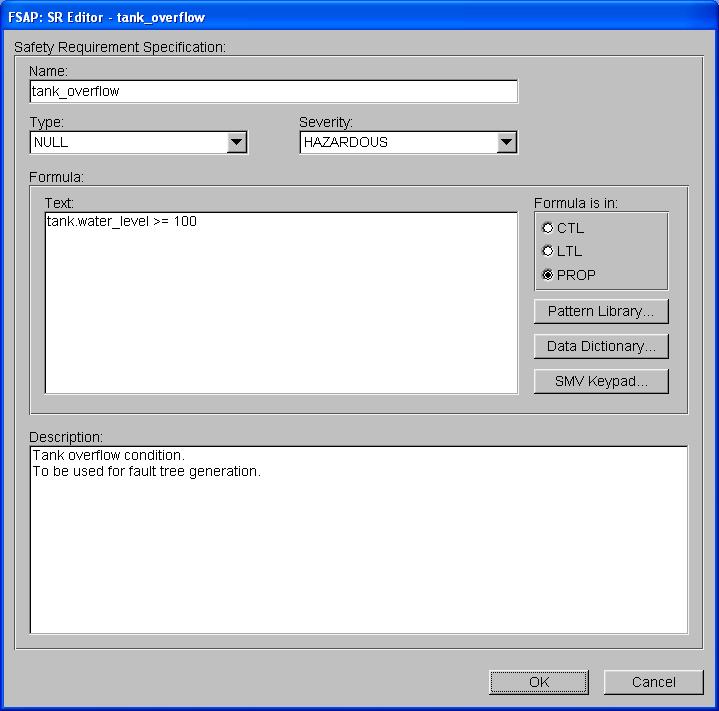
Data Displayed. The SR editor visualizes the following fields for a given SR:
Name
Severity (Null, Minor, Mayor, Hazardous, Catastrophic)
Type (Classification, Segregation, Propagation, Detection)
Formula Text (a temporal formula)
Formula Notation (radio buttons for CTL, LTL, and PROP[ositional] respectively)
Description (a string)
Commands Available.
|
OK |
Add (or accept the changes to) the SR to the SAT. |
|
Cancel |
Cancel the operation. |
|
Pattern Library... |
Open the dialog for instantiating safety patterns from the pattern library. If a safety pattern is chosen and correctly instantiated then it is copied into the formula text field. The user is prompted to replace or append modifications if the text formula already contains text. See also here. |
|
Data Dictionary... |
Open the data dictionary browser. If a variable is chosen within the data dictionary, then it will be automatically copied to the text formula field. See also here. |
|
SMV_Keypad |
Pop up a window where the user can select the operators commonly used for writing NuSMV properties (including those from the CTL and LTL logic languages). See also here. |
The Pattern Library editor allows users:
to select one of the safety patterns contained within the GSRL that is loaded by the tool
to instantiate the selected pattern with opportune values
to accept and copy the ground pattern into the formula text field of the safety requirement dialog that invoked the safety pattern editor
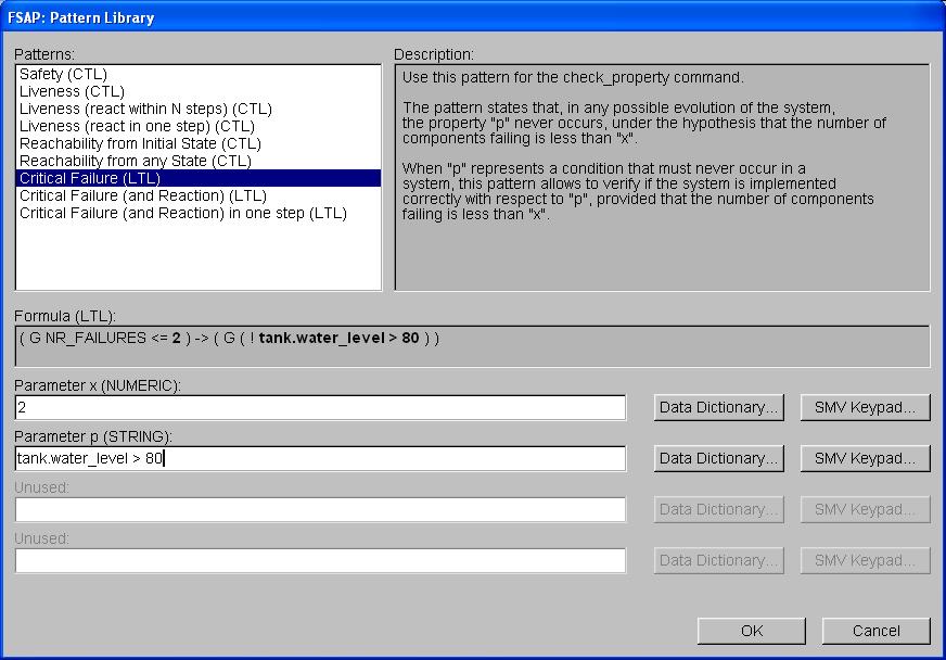
Data Displayed. The Pattern Library editor visualizes the following fields:
Safety Patterns list
Formula of the currently selected SP (includes the notation of the formula and is active: gets refreshed automatically as user interacts with the parameter input boxes)
Parameter input boxes (for instantiating the parameter of the SP formula)
Description (a string)
Commands Available.
|
OK |
Accept the choice of the current safety pattern and copy it to the formula text field of the SR editor. As a side effect, it recognizes the notation of the chosen pattern and makes changes according to the temporal logic selected with the toggle button of the SR editor. |
|
Cancel |
Cancel the operation. |
|
Data Dictionary... |
Open the data dictionary browser. If a variable is chosen within the data dictionary, then it will be automatically copied to the relevant parameter field. See also here. |
The Data Dictionary browser allows users to browse through the symbols defined within the System Model and the Extended System Model and possibly to choose and re-use such symbols in the dialog that invoked the browser itself.
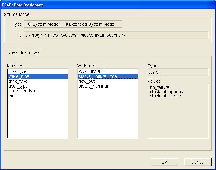
Data Displayed. The DD browser visualizes the following fields:
System Model (if both SM and ESM are available, users can toggle between them: the content of the dialog will be updated conforming to the user choice)
Types Tab (delivers information to the users about typing of variables inside the model, that is to say, resumes the modular structure of the model itself)
Instances Tab (delivers information to the users about all the hierarchically defined variables inside the model)
Type (the type of the currently selected variable, if any)
Values (the possible values that the variable can assume)
Commands Available.
|
OK |
Accept current choice. The result depends upon the module of the platform that invoked the DD. (see also the other sections of this document). |
|
Cancel |
Cancel the operation. |
In particular four different usages of the Data Dictionary can be envisaged:
selecting a NuSMV node (a module/variable pair) from the FM Editor dialog
selecting NuSMV variables and values to use them in several different FSAP dialogs
selecting NuSMV variable/value pair for a failure mode from the FS Editor dialog
simple browsing of SM and ESM
In the first case users are presented with the Types Tab opened and the System Model selected. Both the Instances Tab and the Extended System Model will not be available at this stage, since they do not make sense in such a context. Users are allowed to switch amongst the different modules in the module browser (the variable browser is updated accordingly at once) and then to switch amongst the different variables (type and values fields are updated accordingly, at once). The OK button copies the module name and the variable name into the relevant field of the FM editor window that invoked the DD.
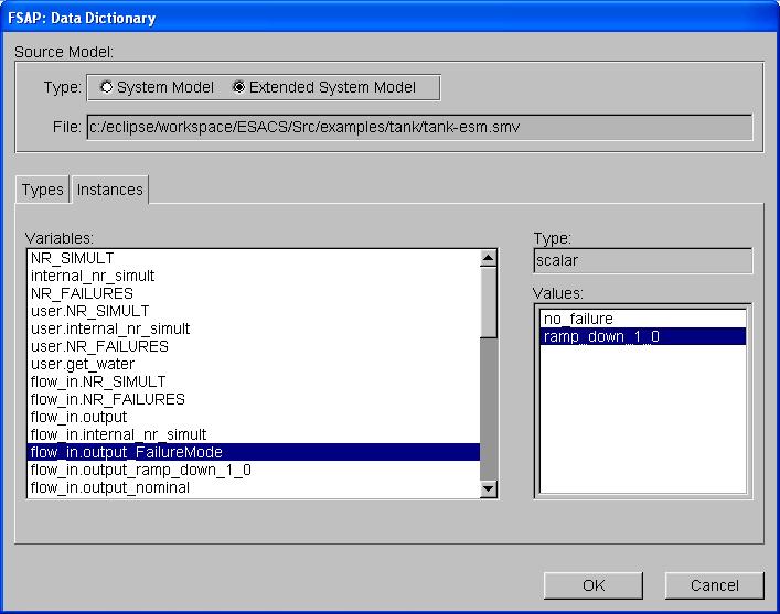
In the second case, the Types Tab is deactivated whilst the Instances Tab is initially open. If possible the SM/ESM choice is active, SM being the default. Users are allowed to switch among the variables presented within the variable browser (type and values fields are updated accordingly, at once). The OK button copies the name of the chosen variable, and the value if selected, into the relevant field of the dialog that invoked the DD (for instance the SR editor, rather than the Pattern Library editor, and so on).
The third case, a variation of the second case, exists when the DD is invoked with 'Add Failure Mode...' button of the Failure Set Editor. For failure sets the user chooses a variable (in this case a failure mode) and also a value for that variable. This variable/value pair is returned to the Failure Set Editor.
The last case is triggered when the DD is invoked from the main FSAP menu. Contrary to the two previous cases, no filtering is performed by FSAP on the usability of the dialog. If any data is available (the ESM might not have been generated, for instance) it is made available to the users. The OK button will have the same result (void) as the Cancel button.
REMARK: the DD might not be available at all. In this case FSAP emits an alert message and appends the motivation for not being able to open the DD browser to the log window.
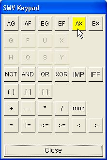
The SMV Keypad is a helpful and fast interface to the standard logical and mathematical operators that are necessary for writing properties in the SMV language. It can be invoked from within the SR editor in order to ease the formulation of the text of the SR.
Symbols are represented by buttons that are highlighted when the mouse hovers over them. When a button is clicked, the corresponding label is copied to the formula text field of the SR dialog which invoked the keypad. Otherwise the 'Close' button is available to exit the keypad with no effect on the SR editor.
Symbols from the CTL and LTL logic languages are activated or deactivated depending on the notation (CTL, LTL, or propositional) currently active within the invoking dialog. Standard first-order logic symbols are always available as well as the usual mathematical operators.
The Analysis Task Manager (AT Manager) allows defining and editing (Safety) Analysis Tasks. Safety Analysis Tasks are the interface to simulation, verification, and safety assessment of the system model. Users can choose whether to store Analysis Tasks (in order to reuse them later on) or just to dismiss them, once the analysis has been performed.
There are various ways for defining and using Analysis Tasks:
Defining a new Safety Analysis Task. It can be done in two different ways:
Using the menu "Analysis": in this case the user needs to choose a safety requirement and then from the "Analysis" menu the kind of analysis to be performed. The Analysis Task dialog is then shown: see section "Managing Analysis Tasks" for more details.
Selecting the "Analysis Task" tab and then clicking on the "New" button. Then the user is presented with a dialog that allows to choose both the type of analysis to be performed and, if required, the safety requirement to use:
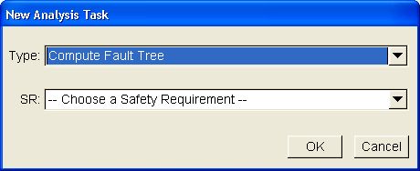
Reusing an existing Safety Analysis Task. In this case, it is sufficient to choose the "Analysis Task" tab and either double-click on the analysis task or select an analysis task and click on the "Edit" button.
The properties that characterize an AT are split into five tabs: the "Analysis" tab, the "Engine" tab, the "Task Info" tab, the "Hypotheses" tab, and the "Execution Options" tab. The content of the "Analysis" tab depends upon the kind of analysis to perform; more information is provided in the "Controlling Analysis" section (the next section). The content of the "Engine" tab varies slightly with the kind of analysis to perform, some analysis allows either BDD-based or SAT-based verification; more information is provided in the "Analysis Engine" section. The "Task Info" tab contains information related to storing an Analysis Task and it's common to all types of analysis; more information is provided in the "Storing Analysis" section. The content of the "Hypotheses" tab provides constraints specifications and is common to all types of analysis; more information is provided in the "Analysis Task Hypotheses" section. Finally "Execution Options" tab contains information about the NuSMV execution of the task; more information is provided in the "Executing Analysis" section.
Analysis tasks have buttons that allow the user to perform the following actions:
|
Run |
Run the Analysis. |
|
Show Results |
Invoke the Result Extraction and Display tools on the analyses. |
|
Save TASK |
Save the analysis so that it can be reused later on. |
|
Close |
Close the window. |
Some Analysis Tasks are limited by the type of engine (BDD or SAT [see Choosing Analysis Engine below]) and/or the formula notation (CTL, LTL, or propositional) that can be used. For example CTL notation can only be used for CHECK PROPERTY analysis tasks with the BDD engine, or FAULT TREE ANALYSIS requires a propositional formula, or SAT-based analysis requires an LTL formula. The following table summarizes which notation and engine can currently be used with which Analysis Tasks (note: propositional formulas include those written in CTL and LTL. So a Safety Requirement written in LTL implies 'LTL and PROP').
| CHECK PROPERTY | FTA/FAULT ISOLATION | |
|---|---|---|
| BDD engine | CTL, LTL (PROP implicitly) | PROP |
| SAT engine | LTL (PROP implicitly) | PROP |
The “Analysis” tab collects the information that is used as parameters for the analysis. The fields that appear within the window depend upon the type of the analysis to be performed and are detailed below.
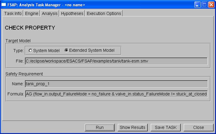
CHECK PROPERTY. The check property dialog is used to verify
properties on the SM or on the ESM.
The information shown is
the following:
|
Target Model: |
The model that will be used by the NuSMV 2 model checker to perform the analysis. The user can choose the SM or the ESM as the Target Model using the radio buttons. |
|
SR: |
The name and the formula of the SR that is used to perform the AT. The safety requirements are chosen when defining an analysis task (see "Defining Analysis Tasks") and cannot be changed once chosen. |
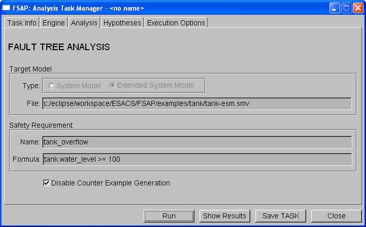
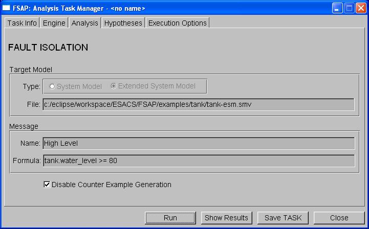
FAULT TREE ANALYSIS and FAULT ISOLATION ANALYSIS. The fault tree analysis and fault isolation analysis dialogs are used to
compute fault trees.
The information shown is the following:
|
Target Model: |
The model that will be used by the NuSMV 2 model checker to perform the analysis. The only model on which it is possible to construct fault trees is the Extended System Model; this option cannot be changed by the user. |
|
SR/Message: |
The name and the formula of the SR or Message that is used to perform the AT. The safety requirements/messages are chosen when defining an analysis task (see "Defining Analysis Tasks") and cannot be changed once chosen. |
|
Preferences: |
Select to disable counter example generation, which should speed up analysis task runtime. |
|
Remark. |
It may be useful to remember that this fault tree construction is influenced by the “Model Monotonicity” property that can be set in SAT Manager window. |
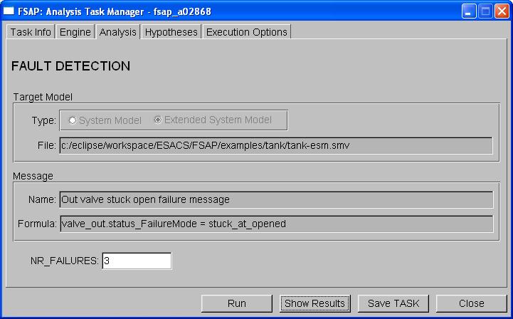
FAULT DETECTION ANALYSIS. The fault detection analysis dialog is used to
compute an FMEA table, which is output in a tab-delimited text file.
The information shown is the following:
|
Target Model: |
The model that will be used by the NuSMV 2 model checker to perform the analysis. It is only possible to compute the FMEA table using the Extended System Model; this option cannot be changed by the user. |
|
Message: |
The name and the formula of the Message that is used to perform the AT. The messages or message classes are chosen when defining an analysis task (see "Defining Analysis Tasks") and cannot be changed once chosen. |
|
NR_FAILURES: |
This option defines the number of failures shown in the FMEA table which lead to a given message (i.e. if NR_FAILURES is set to '3' then the FMEA computation will return all combinations of three failures or less which lead to Message X). |
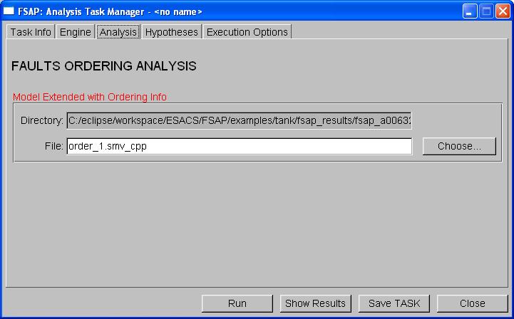
FAULTS ORDERING ANALYSIS. The faults ordering analysis dialog
is used to verify whether there is any particular temporal ordering on
the failures of a given cut set.
Every time NuSMV-SA computes a
fault tree, it generates, for any minimal cut set it finds, a model,
called "ordering information model". This model can be used to
verify whether, in all possible runs in which the cut set causes the
TLE of the fault tree, it is the case that some of the failures of
the cut sets occur in a particular order. Given a fault tree with
cuts sets "Fault_Configuration_1", ...,
"Fault_Configuration_N" the NuSMV-SA model checker
generates the "ordering information models" called
"order_1.smv", ..., "order_N.smv". These files
can be given as input to the "Faults Ordering Analysis"
task to verify if there is any ordering on the events of a minimal
cut sets.
The information shown is the following:
|
File: |
Name of the NuSMV file on which the ordering analysis is to be performed. The file can be chosen by the user with the "Choose" button. |
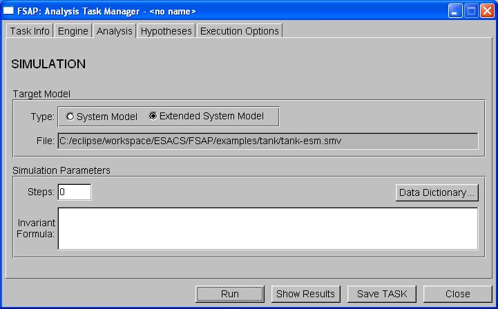
SIMULATION. The simulation dialog is used to perform
simulations on the system model or on the extended system model.
The
information shown is the following:
|
Target Model: |
The model that will be used by the NuSMV 2 model checker to perform the analysis. The user can choose the Target Model between the SM and the ESM, using the radio buttons. |
|
Steps: |
The number of steps that will be performed during the simulation. |
|
Invariant Formula: |
A propositional formula that constrains the simulation only to those runs in which the formula is “true” in every single state. A hook to the Data Dictionary browser is provided through a button, in order to ease the stating of the formula. |
The "Engine" tab contains the radio buttons where the user can choose to use the BDD-based verification engine or the SAT-based verification engine. Both of these are provided by the NuSMV model checker. The SAT-based engine provides model checking using propositional satisfiability. Three different SAT-based engines are available: sim, minisat (the default SAT solver), and zchaff. Zchaff is for non-commercial purposes only. Commercial use of this product is not allowed without permission from the author. For more information on zchaff see http://www.ee.princeton.edu/~chaff/ or contact Sharad Malik (malik @ ee.princeton.edu) for details. For more information on minisat visit the MiniSat webpage or contact Niklas Een or Niklas Sorensson {een,nik} @ cs.chalmers.se.
Not all analysis tasks support both verification engines however. In short, the BDD-based engine can always be used but the SAT-based engine can be used only for CHECK PROPERTY, COMPUTER FAULT TREE, and FAULT ISOLATION analysis tasks; this is detailed below.
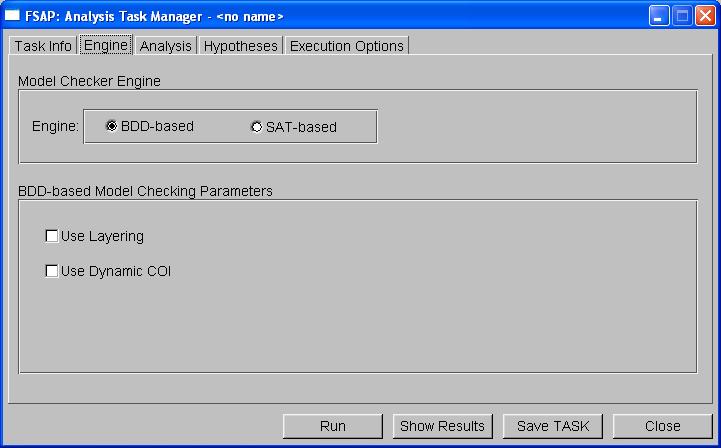
For all analysis tasks you will be able
to select the verification engine. If BDD-based is selected you will see the window above, or a window similar
to the one above. For
faults ordering, fault detection, and simulation, BDD is the only option available and 'SAT-based' will be grayed-out.
For the remaining analysis tasks, BDD is the default option but SAT-based can also be chosen (see below).
The following information can be controlled from the "Engine" tab:
|
Model Checker Engine |
Select the verification engine: BDD or SAT. |
When BDD is selected for monotonic analyses that generate a fault tree, the optimizations 'Use Layering' and 'Use Dynamic COI' are available with a checkbox.
|
BDD-based Model Checking Parameters |
|
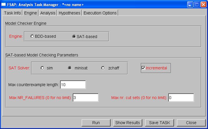
CHECK PROPERTY, FAULT TREE ANALYSIS, and FAULT ISOLATION ANALYSIS. For these three analysis tasks
you can choose SAT-based verification in addition to BDD-based. The selection of the SAT engine
provides further control on how the SAT engine is run.
The following parameters can be controlled from the "Engine" tab when SAT-based verification
is available and has been selected:
|
SAT-based Model Checking Parameters |
Select parameters to further control how the SAT-based engine is run.
|
The "Task Info" tab collects the generic information that is common to all AT and controls how Analysis Tasks are stored.
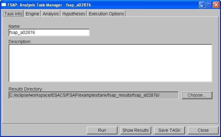
The following information can be controlled from the "Task Info" tab:
|
Name: |
Name of the Analysis Task. It is used as a reference for storing the Analysis Task. |
|
Description: |
Description of the Analysis Task. It is used as a reference for the user. |
|
Results Directory: |
The pathname of the directory where all the results will be stored. This field can be automatically computed by the system or chosen by the user. The behavior is as follows:
The user can choose, using the "Choose" button, the content of the "Results Directory" field. Users can choose either an existing or a non-existing directory. Choosing an existing directory is not destructive, as only the files related to the analysis will be deleted and overwritten. |
|
Remark 1. |
The choose button changes the directory in which the next analysis will store the results. As a consequence, for instance, if you run an analysis and then change the result directory, the results of the last run will not be moved into the new directory. You need to choose the "Run" button once again. |
|
Remark 2. |
None of the fields mentioned above are necessary to run an analysis. They are however necessary to store analysis tasks. |
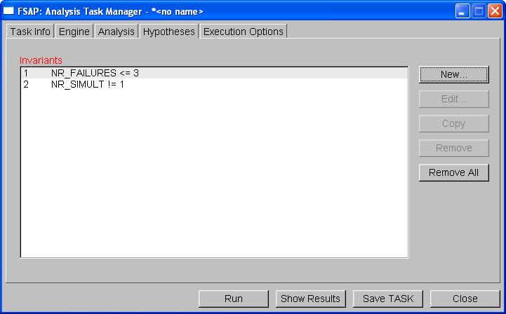
Users can specify constraints for each Analysis Task, achieving a finer-grained control over the execution of the AT. Constraints are defined in the "Hypotheses" tab of the AT dialog in the form of NuSMV invariants formulae. Hypotheses are saved into the SAT and their definition can take advantage of the "Data Dictionary" and "SMV Keypad" facilities.
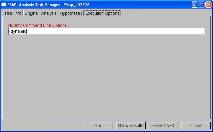
The "Execution Options" tab collects all the information that allows a finer-grained interaction with the NuSMV engine that runs the analysis. At present it is only possible to specify a string containing options that are directly passed to the NuSMV command line.
The Results Extraction and Displayer tools are a set of tools to display the results produced during the analyses.
The main access point for the information generated during the analyses is the "Result Displayer", that can be launched both from the “Tools” menu in the SAT Manager window and from the “Show Results” button in the Analysis Task Manager window.
The "Result Displayer" scans through a directory (either specified by the user or, by default, the last directory created by an execution of an analysis) and recognizes and shows all the files generated by an analysis. The output from NuSMV – a text file copy of the standard output seen in the terminal window – can also be seen in the Results Displayer for each analysis.
The Results Displayer also shows a summary of the analysis in the top pane.
Information in this summary file includes: type of analysis run, the date and time the analysis was run,
whether the analysis was successfully completed or not, and possibly other information
relevant to the type of analysis run. For 'check property' analyses the summary file specifies if
the given property is TRUE or FALSE; for 'fault tree analysis', the probability of the Top Level Event
and the number of cut sets are given; for 'fault isolation', the Fault Isolation Index is given;
and for 'fault detection', the Fault Coverage Index is given. Because the results of
the 'ordering' analysis task are included in the directory of the fault tree to which they are
associated, the summary of the ordering task is appended to the existing summary file in that
directory. Additionally, separate nusmv_out text files are saved for the NuSMV output of
each ordering analysis that is run.
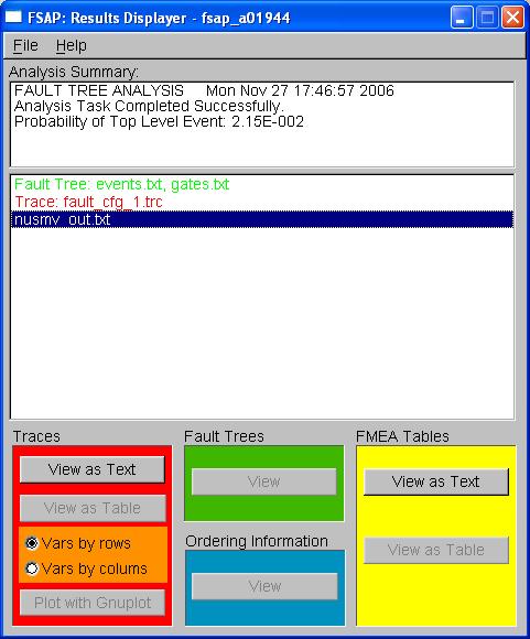
Clicking an item within the list triggers the (de-)activation of
the buttons in the lower part of the application window, that can be
used to invoke different viewers or double-clicking will open the files in
a default viewer. The one exception to this is the nusmv_out.txt file, which, when highlighted,
can be opened with any of the "View as Text" buttons.
In particular, the following table applies:
|
Color Coding: Red |
Color Coding: Green |
Color Coding: Blue |
Color Coding: Yellow |
||||
|---|---|---|---|---|---|---|---|
|
Result Type: |
Traces |
Result Type: |
Fault Trees |
Result Type: |
Ordering Info |
Result Type: |
FMEA Tables |
|
Meaning: |
Traces that shows how a minimal cut set causes a TLE |
Meaning: |
Fault tree related to a TLE. |
Meaning: |
Ordering information about a minimal cut set. |
Meaning: |
FMEA table related to a message or TLE. |
|
Actions |
Actions |
Actions |
Actions |
||||
|
View as Text: |
View the trace using the default text editor. |
View: |
View the fault tree using the built-in fault tree viewer. See "Fault Tree Displayer" section for more details. |
View: |
View the ordering information using the default text editor. |
View as Text: |
View the tabbed file using the default text editor. |
|
View as Table: |
View the trace in tabular form (either organized by rows or by columns), using the default spreadsheet. |
|
|
|
|
View as Table: |
View the tab-delimited file using the default spreadsheet. |
|
Plot w/ Gnuplot: |
Plot the trace using Gnuplot and an interface to it called FSAP plotter. See "Plotting Traces" section for more details. |
|
|
|
|
|
|
The applications used as default viewers (with the exception of
the fault tree displayer), can be set using the Preference module,
described in the "Preference
Module" section.
The Result Displayer menu is organized as follows:
|
File |
> |
Open directory... |
Open the directory where results have been previously saved. |
|
|
|
Exit |
Close the Result Displayer window. |
|
Help |
> |
Contents |
Opens this document |
|
|
|
Release Notes |
Opens information about what's new. |
|
|
|
FSAP on the Web |
Opens the home page of the FSAP/NuSMV-SA tool. |
|
|
|
About |
Shows some information about the FSAP/NuSMV-SA tool. |
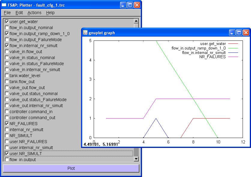
The FSAP platform includes a means for plotting the counterexamples generated within the platform. The module devoted to this functionality has been obtained by integrating an internal tool called Plotter with the well-known Gnuplot plotter.
The Plotter shows to the user the list of variables that occur within a particular trace. The Plotter can be launched both from the Tools menu in the SAT Manager window and with the “Plot with Gnuplot” button for traces in the Results Displayer window. In the former case the trace must be chosen from the user by opening the "File" menu and selecting the item "Open", while in the latter case the trace is selected by the user within the Result Displayer browser.
Variables are shown in the fashion of check buttons so that the user can easily declare what are the variables of interest. Users can also check and save certain variables as 'default' variables, which allow users to easily graph different traces with the same variables. This is done by checking the desired variables and selecting "Set default variables" under the "Actions" menu. The "Edit" menu provides the user with shortcuts for selecting variables, by checking all the variables ("Check all" item), checking none of them ("Clear all" item), inverting the current selection ("Invert" item), or checking the variables that have been defined as 'defaults variables' ("Load default variables" item).
The plotting of the trace can then be invoked either by clicking the "Plot" button at the bottom of the window, by choosing the "Plot" item in the "Actions" menu, or even with the shortcut F5. At this point FSAP invokes Gnuplot with the appropriate options and lets the plot appear as it can be seen below. Just close the window with the upper right standard close box to get back to the Plotter dialog.
REMARK: even though non numeric variables can be chosen within the Plotter for the sake of completeness, only numeric variables will be correctly plotted by Gnuplot.
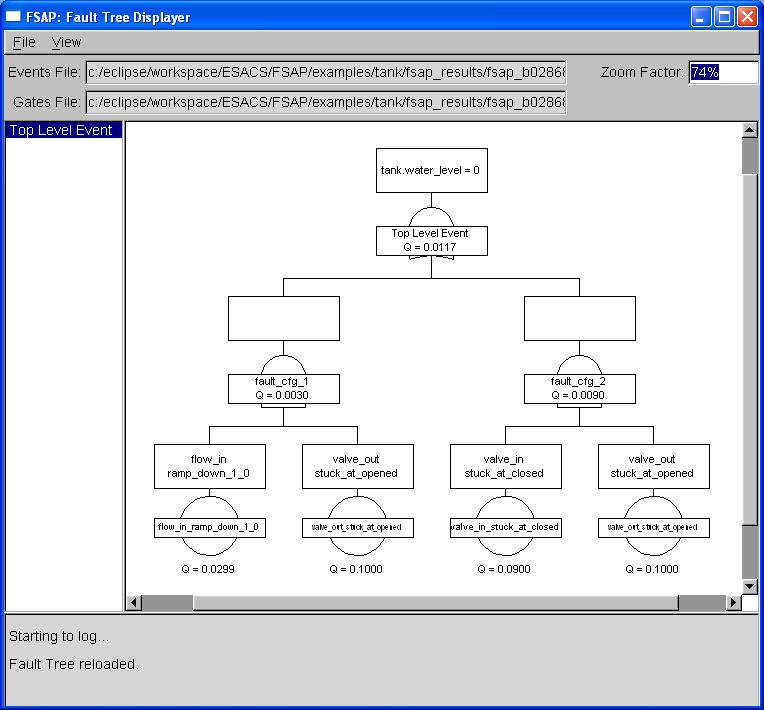
The FT displayer is used to show fault trees generated by the FSAP/NuSMV-SA (in Fault Tree+ compatible format). It can be launched both from the “Tools” menu in the SAT Manager window and from the “View” button for Fault Trees in the Results Displayer window.
 |
 |
Data Displayed. The FTD browser visualizes the following fields:
Commands Available. Actions are performed using the menu items or interacting with the dialog controls.
The Fault Tree Displayer menu is organized as follows:
|
File |
> |
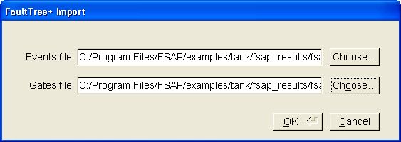
Open... |
Open a fault tree stored in FT+ exchange format. A dialog is opened in which users must specify the events file and gates file. |
|
|
|
Reload |
Reload the currently opened fault tree. |
|
|
|
Export... |
Export the current fault tree in SVG format. |
|
|
|
Close |
Close/Unload current fault tree leaving the displayer opened. |
|
|
|
Exit |
Exit the fault tree displayer. |
|
Actions |
> |
Open Counterexample... |
Opens the Result Displayer, highlighting the trace file of the selected node (if it exists). |
|
|
|
Compute Ordering... |
Opens an ordering analysis task for the selected node (if an ordering file exists). |
|
View |
> |
Zoom In |
Increases 'Zoom Factor' by 20%. |
|
|
|
Zoom Out |
Decreases 'Zoom Factor' by 20%. |
|
|
|
Full Size |
Sets 'Zoom Factor' to 100%. |
|
|
|
Hide/Show Probability |
Makes visible or not the probability of all events in the fault tree. |
Interaction with the dialog comprises:
Zoom factor:
When loading a fault tree from scratch, or when reloading it, the zoom factor is set to a value that allows the vision of the entire fault tree (might be quite small if the fault tree is wide or deep)
Any positive value then can be inserted in the zoom factor input box ('%' symbol is automatically appended if the user does not provide it)
The zoom factor can also be easily adjusted by double-clicking the graph to quickly zoom in, or using the zoom in/zoom out shortcuts.
Depending upon the structure of the tree, there exists an upper bound for the zoom factor (due to the limit imposed by FLTK library to the size of the canvas) above which the FTD declares its inability to completely draw the fault tree. The tree gets clipped and an alert box is issued
Pages:
The FTD can manage the paging of a fault tree
If the gates file contains info about paging, the list of such page gates gets displayed in the browser on the left of the window
Clicking a page results in displaying the subtree that departs from that gate
The top gate by default is considered a page gate and is always present within the page browser
Remarks on FSAP/NuSMV-SA and FaultTree+:
Remark on SVG export:
The SVG file export from the Fault Tree Displayer is best viewed with Adobe's SVG
viewer plugin with Internet Explorer.
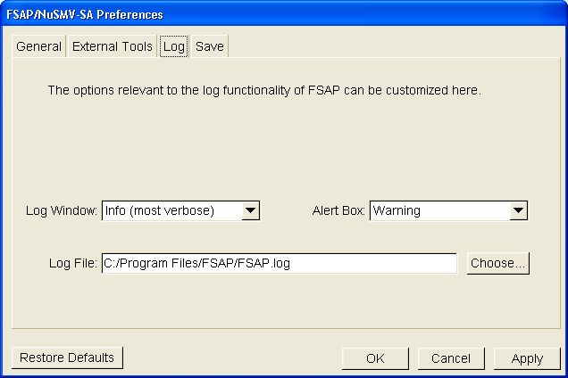
The Log module provides a communication channel from the platform to the user both by recording the activities performed and giving feedback on them such as error, warning, and info messages.
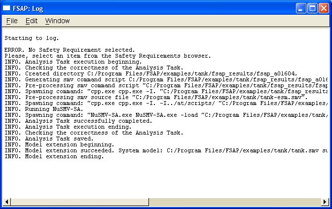
It is essentially a text display window into which messages are appended. The window is scrolled so to show the last message. Some kind of interaction is available to the user in order to control this feature.
Commands Available. Actions are performed using the menu items.
The Log Window menu is organized as follows:
|
File |
> |
Save |
Flushes current content of the Log window to the file specified in the preferences |
|
Edit |
> |
Status |
Log information about the status of the log functionality, such as levels, log file... |
|
Window |
> |
Clear |
Clear the window, restarting logging from scratch |
|
|
|
Iconify |
Iconify the log window. |
|
|
|
Hide |
Hide the log window. The window is NOT permanently deleted. It can be brought back to the screen using the Window menu of the SAT manager. |
Controlling the Log window is possible also through the "Log" menu item in the "Window" menu of the SAT manager.
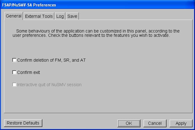
The Preferences module allows the user to control several different aspects of the application. It is made of four tabs, each addressing a different feature of the platform.
Here is a brief summary of the configurable options grouped by the relevant tab:
General (options referring to generic aspects of the platform):
The ESM Preferences allows the user to control what is included in the Extended System Model. This window is opened from the 'Actions' menu in SAT.
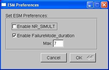
The preferences available for customizing the ESM are:
There is usually no need to access the NuSMV-SA tool from the command line, as FSAP provides an interface to the model checker. However, in certain situations it may be useful to have direct access. This section provides a reference for some NuSMV2 commands used in the NuSMV-SA platform, in particular related to the following activities:
For a complete reference to the commands available with NuSMV-SA, please refer to the NuSMV2 documentation, available from the NuSMV2 home page (http://nusmv.fbk.eu/)
The compute_fault_tree is the command to compute
fault trees for monotonic systems, using the standard BDD-based engine.
usage: compute_fault_tree [-h] [-m| -o file] [-g] [-t] [-e] [-p] [-x "prefix_string"]"simple-expr"
   -h           Prints the command usage
   -m           Pipes output through the program specified by
                the "PAGER" shell variable if defined,
                 else through UNIX "more"
   -o file      Writes the generated output to "file"
   -g           Generates extended models with ordering variables
   -t           Generates fault tree
   -e           Prints counterexample traces
   -p           Computes probability
   -x prefix    Prefixes generated file names with "prefix"
   simple-expr  Print min terms of simple-expr
Example
NuSMV > set input_file sps-ext_cpp.smv
NuSMV > go
NuSMV > compute_fault_tree -e -t "Gb.speed = 0"
The compute_fault_tree_bmc is the command to compute
fault trees for monotonic systems, using the SAT-based engine.
usage: compute_fault_tree_bmc [-h] [-m| -o file] [-k length] [-l loopback] [-n mcs] [-N NR_FAIL] [-g] [-t] [-e] [-x "prefix_string"]"simple-expr"
   -h           Prints the command usage
   -m           Pipes output through the program specified by
                the "PAGER" shell variable if defined,
                 else through UNIX "more"
   -o file      Writes the generated output to "file"
   -k length    set problem length to length
   -l loop      set loopback value to loop
   -n mcs       limit number of cut sets to be computed to mcs
   -N NR_FAIL   limit number of possible failures to NR_FAIL
   -g           Generates extended models with ordering variables
   -t           Generates fault tree
   -e           Prints counterexample traces
   -p           Computes probability
   -x prefix    Prefixes generated file names with "prefix"
   simple-expr  print min terms of simple-expr
Example
NuSMV > set input_file sps-ext_cpp.smv
NuSMV > go_bmc
NuSMV > compute_fault_tree_bmc -e -t "Gb.speed = 0"
The compute_fault_tree_bmc_inc is the command to compute
fault trees for monotonic systems, using the SAT-based engine and incremental verification (requires an incremental SAT solver).
usage: compute_fault_tree_bmc_inc [-h] [-m| -o file] [-k length] [-l loopback] [-n mcs] [-N NR_FAIL] [-g] [-t] [-e] [-x "prefix_string"]"simple-expr"
   -h           Prints the command usage
   -m           Pipes output through the program specified by
                the "PAGER" shell variable if defined,
                 else through UNIX "more"
   -o file      Writes the generated output to "file"
   -k length    set problem length to length
   -l loop      set loopback value to loop
   -n mcs       limit number of cut sets to be computed to mcs
   -N NR_FAIL   limit number of possible failures to NR_FAIL
   -g           Generates extended models with ordering variables
   -t           Generates fault tree
   -e           Prints counterexample traces
   -p           Computes probability
   -x prefix    Prefixes generated file names with "prefix"
   simple-expr  Print min terms of simple-expr
Example
NuSMV > set input_file sps-ext_cpp.smv
NuSMV > go_bmc
NuSMV > set sat_solver zchaff
NuSMV > compute_fault_tree_bmc_inc -e -t "Gb.speed = 0"
The compute_prime_implicants command is the command
to compute fault trees for non monotonic systems, using the standard BDD-based engine.
usage: compute_prime_implicants [-h] [-f] [-m| -o file] [-g] [-t] [-e] [-x "prefix_string"] "simple-expr"
   -h           Prints the command usage
   -f           Existentially quantify over non-failure variables
   -m           Pipes output through the program specified by
                the "PAGER" shell variable if defined,
                 else through UNIX "more"
   -o file      Writes the generated output to "file"
   -g           Generates extended models with ordering variables
   -t           Generates fault tree
   -e           Prints counterexample traces
   -p           Computes probability (requires option -f)
   -x prefix    Prefixes generated file names with "prefix"
   simple-expr  print min terms of simple-expr
Example
NuSMV > set input_file sps-ext_cpp.smv
NuSMV > go
NuSMV > compute_prime_implicants -f -e -t "Gb.speed = 0"
The compute_fmea_table command is the command
to compute fmea tables, using the standard BDD-based engine.
usage: compute_fmea_table [-h] [-m| -o file] [-N NR_FAIL] [-t] [-x "prefix_string"]
   -h           Prints the command usage
   -m           Pipes output through the program specified by
                the "PAGER" shell variable if defined,
                 else through UNIX "more"
   -N NR_FAIL   set number of failures to NR_FAIL (default: 1)
   -o file      Writes the generated output to "file"
   -t           Generates fmea table
   -x prefix    Prefixes generated file names with "prefix"
Example
NuSMV > set input_file sps-ext_cpp.smv
NuSMV > go
NuSMV > compute_fmea_table -t
The compute_ordering command is the command to verify
whether there is any ordering on the failures related to a minimal
cut set. It requires having run one of the following commands compute_fault_tree,
compute_fault_tree_bmc, compute_fault_tree_bmc_inc, or
compute_prime_implicants with the -g option beforehand.
usage: compute_ordering [-h] [-m| -o file] "file_name"
   -h           Prints the command usage
   -m           Pipes output through the program specified by
                the "PAGER" shell variable if defined,
                 else through UNIX "more"
   -o file      Writes the generated output to "file"
   file_name    Analyze ordering for model in file "file_name"
Example
NuSMV > set input_file sps-ext_cpp.smv
NuSMV > go
NuSMV > show_vars -s
NuSMV > compute_prime_implicants -f -g -e "SPS_LH.GB.W_gb = 0"
NuSMV > !cpp order_9_sps-ext_cpp.smv > order_9_sps-ext_cpp_cpp.smv
NuSMV > compute_ordering order_9_sps-ext_cpp_cpp.smv
The check_ctlspec command is the NuSMV command to
verify a property expressed in CTL, using the standard BDD-based engine.
usage: check_ctlspec [-h] [-m | -o file] [-n number | -p "ctl-expr"]
   -h               Prints the command usage.
   -m               Pipes output through the program specified
                    by the "PAGER" environment variable if defined,
                    else through the UNIX command "more".
   -o file          Writes the generated output to "file".
   -n number        Checks only the SPEC with the given index number.
   -p "ctl-expr"    Checks only the given CTL formula.
Example
NuSMV > set input_file sps-ext_cpp.smv
NuSMV > go
NuSMV > check_ctlspec -p "AG(Gb.speed=0 -> Gb.speed_FailureMode != no_failure)"
The check_ltlspec command is the NuSMV command to verify a
property expressed in LTL, using the standard BDD-based engine.
usage: check_ltlspec [-h] [-m | -o file] [-n number | -p "ltl_expr"]
   -h                   Prints the command usage.
   -m                   Pipes output through the program specified by
                        the "PAGER" environment variable if any,
                        else through the UNIX command "more".
   -o file              Writes the debugger output to "file".
   -n number            Checks only the LTLSPEC with the given index number.
   -p "ltl-expr"        Checks only the given LTL formula.
Example
NuSMV > set input_file sps-ext_cpp.smv
NuSMV > go
NuSMV > check_ltlspec -p "G(Gb.speed=0 -> Gb.speed_FailureMode != no_failure)"
The check_ltlspec_bmc command is the NuSMV command to
verify a property expressed in LTL, using the SAT-based engine.
Usage: check_ltlspec_bmc [-h | -n idx | -p "formula"] [-k max_length] [-l loopback] [-o <filename>]
  -h            Prints the command usage.
  -n idx        Checks the LTL property specified with <idx>.
  -p "formula"  Checks the specified LTL property.
                If no property is specified, checks all LTL properties.
  -k max_length Checks the property using <max_length> value instead of using the
                variable <bmc_length> value.
  -l loopback   Checks the property using <loopback> value instead of using the
                variable <bmc_loopback> value.
  -o filename   Generates dimacs output file too. <filename> may contain patterns.
Example
NuSMV > set input_file sps-ext_cpp.smv
NuSMV > go_bmc
NuSMV > check_ltlspec_bmc -p "G(Gb.speed=0 -> Gb.speed_FailureMode != no_failure)"
The check_ltlspec_bmc_inc command is the NuSMV command to
verify a property expressed in LTL, using the SAT-based engine and
incremental verification (requires an incremental SAT solver).
Usage: check_ltlspec_bmc_inc [-h | -n idx | -p "formula"] [-k max_length] [-l loopback]
  -h            Prints the command usage.
  -n idx        Checks the LTL property specified with <idx>.
  -p "formula"  Checks the specified LTL property.
                If no property is specified, checks all LTL properties.
  -k max_length Checks the property using <max_length> value instead of using the
                variable <bmc_length> value.
  -l loopback   Checks the property using <loopback> value instead of using the
                variable <bmc_loopback> value.
Example
NuSMV > set input_file sps-ext_cpp.smv
NuSMV > go_bmc
NuSMV > set sat_solver zchaff
NuSMV > check_ltlspec_bmc_inc -p "G(Gb.speed=0 -> Gb.speed_FailureMode != no_failure)"
The pick_state and simulate commands are
the NuSMV commands for simulating a model.
usage: pick_state [-h] [-v] [-r | -i [-a]] [-c "constr"]
  -h            Prints the command usage.
  -v            Verbosely prints picked state.
  -r            Randomly picks a state from the set of the initial states
                (otherwise choice is deterministic).
  -i            Lets the user interactively pick a state from
                the set of initial ones.
  -a            Displays all the state variables (changed and
                unchanged) in an interactive session.
                It works only together with -i option.
  -c "constr"   Sets constraints for the initial set of states.
                Note: must be enclosed between double quotes " ".

usage: simulate [-h] [-p | -v] [-r | -i [-a]] [-c "constr"] steps

  -h            Prints the command usage.
  -p            Prints current generated trace (only changed variables).
  -v            Verbosely prints current generated trace (all variables).
  -r            Sets picking mode to random (default is deterministic).
  -i            Enters simulation's interactive mode.
  -a            Displays all the state variables (changed and unchanged)
                in every step of an interactive session.
                It works only together with -i option.
  -c "constr"   Sets constraint (simple expression) for the next steps.
                Note: must be enclosed between double quotes " ".
  steps         Maximum length of the path.
Example
NuSMV > set input_file sps-ext_cpp.smv
NuSMV > go
NuSMV > pick_state -r -c
       "Me.speed_FailureMode = ramp_down_1_4 &
        Gb.speed_FailureMode = no_failure & Atm.speed_FailureMode = no_failure &
        Prsov.status_FailureMode = no_failure"
NuSMV > simulate -r -c
       "Me.speed_FailureMode = ramp_down_1_4 &
        Gb.speed_FailureMode = no_failure & Atm.speed_FailureMode = no_failure &
        Prsov.status_FailureMode = no_failure" 25
NuSMV > show_traces -v -o engine_flameout.trc 1
| AT | analysis task |
| BDD | binary decision diagram; one of the symbolic model checking techniques offered by NuSMV |
| CTL | computation tree logic; temporal logic used to define safety requirements in FSAP/NuSMV-SA |
| DD | data dictionary; collection of symbols and variables used in the system model and/or extended system model |
| ESACS | Enhanced Safety Assessment for Complex Systems; original European project in which FSAP/NuSMV-SA was developed |
| ESM | extended system model; automatically generated system model with the injected failure modes |
| FM | failure mode; definition of what part of the system model can fail and how |
| FMEA | failure mode and effect analysis |
| FSAP | Formal Safety Analysis Platform |
| FT | fault tree; tree representation of events or combinations of events which violate a top level event/system requirement |
| FTA | fault tree analysis; analysis of system requirement which generates a fault tree |
| FTD | fault tree display; graphical representation of fault tree |
| GFML | generic failure mode library; collection of defined failure modes |
| GSRL | generic safety requirements library; collection of defined safety requirements |
| ISAAC | Improvement of Safety Activities on Aeronautical Complex systems; current European project in which FSAP/NuSMV-SA is being developed |
| LTL | linear temporal logic; temporal logic used to define safety requirements in FSAP/NuSMV-SA |
| MCS | minimal cut set; minimum combination of failures which cause a top level event |
| NuSMV | a symbolic model checker |
| NuSMV-SA | extension of NuSMV2 which is used on safety analysis tasks |
| SAT |
1) Safety Analysis Task 2) SAT(satisfiability)-based; one of symbolic model checking techniques offered by NuSMV |
| SM | system model; a model to define the nominal behavior of a system |
| SP | safety pattern; predefined pattern, used as a building block to define safety requirements |
| SR | safety requirement; definition of required behavior in a degraded situation |
| SRS | system requirements specification; document that collects the functional and non-functional requirements of the system being developed |
| SVG | scalable vector graphics; language for describing two-dimensional graphics in XML |
| TLE | top level event; event, in this case a message or safety requirement, to undergo fault tree analysis |
Last Update: $Date: 2008/02/14 14:43:47 $