FAME Process
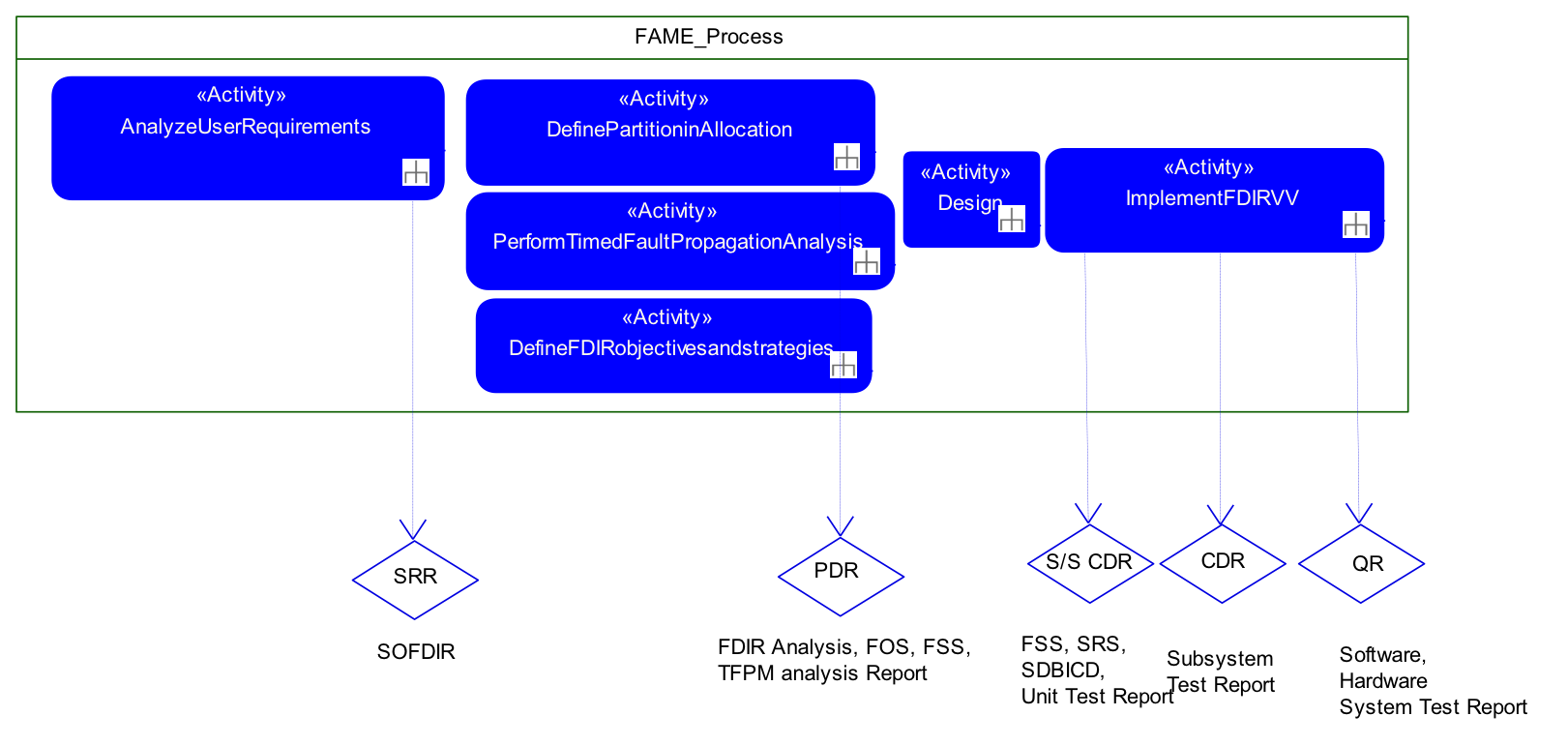
Analyze user requirements
Involved: System engineers
Start: begin of System Phase B
End: before System SRR
- Collect and analyze all the user requirements contained in SRD and OIRD that impact the FDIR to derive the objectives of the FDIR and define the impacts they will have on the S/C design from system level down to unit level.
- Highlight possible limitations.
- System Modeling & Fault Extension: Modeling nominal and faulty behavior
- Formal Analyses: Derive requirements on the design of FDIR
- Mission Modeling: Definition of phases, modes, and S/C configurations
Define partitioning / allocation
Involved: FDIR engineers
Start: after System SRR
End: System PDR
- Allocate RAMS and Autonomy Requirements contained in SOFDIR per Mission Phase/Spacecraft Operational Mode in order to define FDIR approach and Autonomy Concept during different mission phases/Spacecraft Operational Mode.
- Model spacecraft FDIR architecture including all the involved subsystems (avionics, payload, etc).
- System Modeling: Modeling of FDIR, context, scope, architecture
- Formal Analyses: Derive and collect FDIR requirements
FDIR objectives and strategies
Involved: FDIR engineers
Start: after System SRR
End: System PDR
- Specify FDIR Objectives at system-level specification in FOS and FDIR Strategies at subsystem level in FSS by using FDIR Analysis and TFPM Analysis Report.
- FDIR Requirements Modeling: FDIR objectives, strategies, existing components, hierarchy, etc
Perform timed failure propagation analysis
Involved: Safety engineers
Start: System SRR
End: System PDR
- Specifies a timed failure propagation model (TFPM) for the design starting from fault trees, FMEA tables and Hazard Analysis.
- Tasks: Specify TFPM, Analyse TFPM
- Outputs: TFPM analysis Report
- Formal Analyses: Derive information on causality and failure propagation
- TFPM (fault propagation) Modeling: TFPM modeling, editing, viewing
- TFPM Analyses: TFPM behavioral validation, effectiveness validation, synthesis
Design
Involved: FDIR engineers, SW engineers, SDB engineersStart: System PDR
End: S/S CDR Process Objectives
- Design FDIR in the various subsystems, software and database on the base of FDIR Reference Architecture.
- FDIR Modeling & Synthesis: Modeling / Synthesis of FDIR components
- Formal Analyses: FDIR effectiveness validation
Implement FDIR, validate and verify
Involved: S/S engineers, Testing engineers
Start: S/S PDR
End: System QR
- Implement FDIR in hardware or software and validated and verified respect to specifications.
- Contract-based generation of test suites (future work)
FAME Environment
The following figure shows the general workflow in the FAME Environment.
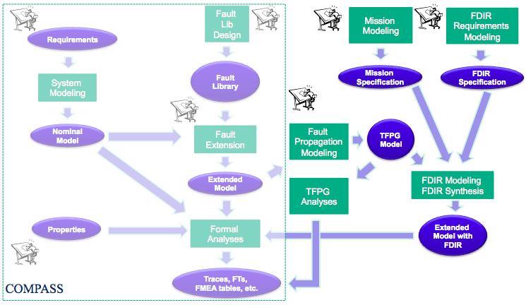
A central component of the FAME process are timed failure propagation models. The specific models that are used in the FAME environment are TFPGs (Timed Failure Propagation Graphs).
The following is a simple example for a system for which a TFPG was derived.
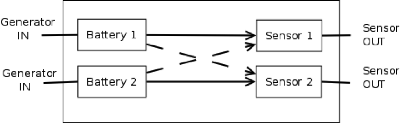
- Generators powering batteries, in turn powering sensors
- Redundant system: 2 Generators, 2 Batteries, 2 Sensors
- At least one sensor must be working, for the system to be alive
- Faults: generators go off, sensors produce wrong output
- Primary Configuration: battery 1 feeding sensor 1, battery 2 feeding sensor 2
- Secondary 1: battery 1 feeding both sensors
- Secondary 2: battery 2 feeding both sensors
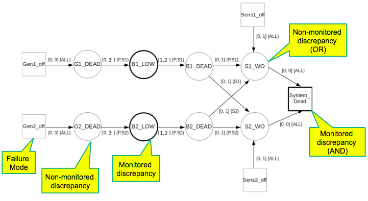
The following TFPG describes the failure propagation in the battery sensor model
(click to enlarge).
- TFPG analyses
- Behavioral validation: tests fidelity of TFPG wrt extended system model.
- Effectiveness validation: tests whether sufficient TFPG nodes are monitored in order to achieve diagnosis objectives (diagnosability).
- TFPG Synthesis: A TFPG can be automatically derived from the extended system model.
- Synthesis of FDIR
- Synthesis of FD components (diagnoser synthesis).
- Synthesis of FR components (synthesis of recovery plans).